The Four Layer Diode

If we add a junction to a transistor, we get a four-layer device. At first glance, this may seem either useless or counter-productive, but this is not the case.


The basic 4-layer diode.

The diagram to the right shows the structure and nomenclature of the four-layer diode, together with its equivalent structure, showing its logical behavior and its schematic symbol. Rather than acting simply as an odd sort of diode, this device actually behaves as two transistors, interconnected back-to-back as shown. The external connections are designated the cathode (n-type connection) and anode (p-type connection). This keeps us from having to distinguish between the n-emitter and the p-emitter.

In operation, the device is placed in a circuit so that the anode is held positive with respect to the cathode. If this voltage polarity is reversed, the four-layer diode exhibits two reverse-biased junctions and will not conduct current.


The applied voltage appears mainly across the reverse-biased center junction of the device, and the quiescent current flowing through the device is quite small, consisting essentially of a leakage current. As the applied voltage increases slowly, the leakage curent increases slowly as well, until the applied voltage reaches a certain level. At this voltage, known as the breakover voltage or firing voltage of the device, the two logical transistors both turn on and current increases dramatically. At the same time, the voltage across the diode decreases to almost zero, and the applied voltage now appears across whatever load circuit or device is connected in series with the diode. The diode has just switched from its off (or blocking) state to its on state.

Once the four-layer diode is conducting, it will continue to conduct as long as current continues to flow. It can only be turned off by reducing the circuit voltage and/or current to below the levels required to sustain conduction. Typically, this means either removing power totally from the circuit, or else using the diode as a device to periodically discharge a capacitor.

The breakover voltage and current-handling capacity of a given four-layer diode are determined by the exact details of its manufacture. Four-layer diodes may be manufactured with a wide range of voltage and current ratings.


There is one problem which can appear with the four-layer diode: if the applied voltage rises rapidly, the inherent capacitance associated with the reverse-biased middle junction will transmit the applied voltage more directly, and cause the diode to switch on at a voltage well below its designed breakover voltage. This phenomenon is known as the rate effect.

Applications for the four-layer diode fall into two categories. In active cirucits, they can be used as the active element in a sawtooth waveform generator or triggered pulse generator. Or, they can be used as a "crowbar" element in a power supply. In this last application, the four-layer diode is placed directly across the output terminals of the power supply, used to power delicate circuitry. If the supply voltage should rise for any reason to a level that might damage the circuitry, the four-layer diode breaks over and draws a heavy current from the supply. This overloads the supply and causes the fuse or circuit breaker to blow. It's a drastic measure, but still much better than allowing expensive circuit components to be damaged or destroyed.

The Diac and Triac

One of the drawbacks of all of the four-layer diodes is that they all require a dc voltage of the correct polarity in order to operate. It would be nice if we could have some sort of SCR that works for either polarity, so it can be used with an applied ac voltage.

Now, we created the four-layer devices by essentially connecting two transistors back to back in a single silicon crystal. Can we extend this concept and connect two SCRs back to back?


Diac construction and symbol.

The diagram to the right shows the resulting five-layer device, which is known as a diac. At first glance, it seems unreasonable or even impossible, considering that each connection to the semiconductor crystal overlaps a pn junction. However, the device does work, and indeed works well.

The terms anode and cathode no longer apply, so the connections are simply named terminal 1 (T1) and terminal 2 (T2). Each terminal can serve as either anode or cathode, according to the polarity of the applied voltage.

That same applied polarity also determines which of the end junctions is active, and which one is bypassed. Thus, if T1 is positive with respect to T2, T1's N-type region is ignored (electrons are pulled away from that junction) and its P-type region serves as the anode. At the same time, the relative negative voltage at T2 pulls holes from the P-type region towards the terminal (removing them from the next junction), but tends to push electrons from its N-type region across that junction into the P-type region, thus making them available for conduction.

The diac, like the four-layer diode, remains non-conducting until its breakover voltage is reached, at which point it turns on fully and remains on until the applied voltage or circuit current are reduced below the holding values at which conduction can be maintained. Since the diac is normally used in ac circuits, operating as part of the control circuit for devices powered from a household wall socket or similar source, this is not a problem. In such applications, the diac is triggered each half-cycle of ac power, and then turns off at the end of the half-cycle when the line voltage reverses polarity.


Triac construction and symbol.

The drawback of the diac is the same as it was for the four-layer diode: it cannot be triggered at just any point in the ac power cycle; it triggers at its preset breakover voltage only. If we could add a gate to the diac, we could have variable control of the trigger point, and therefore a greater degree of control over just how much power will be applied to the line-powered device.

The figure to the right shows the result. This device is known as a triac. Here, the main connections are simply named main terminal 1 (MT1) and main terminal 2 (MT2). The gate designation still applies, and is still used as it was with the SCR.

The useful feature of the triac is that it not only carries current in either direction, but the gate trigger pulse can be either polarity regardless of the polarity of the main applied voltage. The gate can inject either free electrons or holes into the body of the triac to trigger conduction either way. For this reason, you may see the triac referred to as a "four-quadrant" device.


As with the diac, the triac is used in an ac environment, so it will always turn off when the applied voltage reaches zero at the end of the current half-cycle. If we apply a turn-on pulse at some controllable point after the start of each half cycle, we can directly control what percentage of that half-cycle gets applied to the load, which is typically connected in series with MT2. This makes the triac an ideal candidate for light dimmer controls and motor speed controls. This is a common application for triacs.

What Is GPS

The Global Positioning System (GPS) is a satellite-based navigation system made up of a network of 24 satellites placed into orbit by the U.S. Department of Defense. GPS was originally intended for military applications, but in the 1980s, the government made the system available for civilian use. GPS works in any weather conditions, anywhere in the world, 24 hours a day. There are no subscription fees or setup charges to use GPS.

How it works

GPS satellites circle the earth twice a day in a very precise orbit and transmit signal information to earth. GPS receivers take this information and use triangulation to calculate the user's exact location. Essentially, the GPS receiver compares the time a signal was transmitted by a satellite with the time it was received. The time difference tells the GPS receiver how far away the satellite is. Now, with distance measurements from a few more satellites, the receiver can determine the user's position and display it on the unit's electronic map.

GPS Screens

A GPS receiver must be locked on to the signal of at least three satellites to calculate a 2D position (latitude and longitude) and track movement. With four or more satellites in view, the receiver can determine the user's 3D position (latitude, longitude and altitude). Once the user's position has been determined, the GPS unit can calculate other information, such as speed, bearing, track, trip distance, distance to destination, sunrise and sunset time and more.

How accurate is GPS?

Today's GPS receivers are extremely accurate, thanks to their parallel multi-channel design. Garmin's 12 parallel channel receivers are quick to lock onto satellites when first turned on and they maintain strong locks, even in dense foliage or urban settings with tall buildings. Certain atmospheric factors and other sources of error can affect the accuracy of GPS receivers. Garmin® GPS receivers are accurate to within 15 meters on average.

GPS Signals

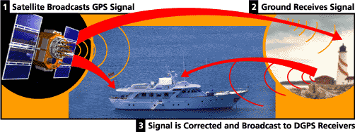
Newer Garmin GPS receivers with WAAS (Wide Area Augmentation System) capability can improve accuracy to less than three meters on average. No additional equipment or fees are required to take advantage of WAAS. Users can also get better accuracy with Differential GPS (DGPS), which corrects GPS signals to within an average of three to five meters. The U.S. Coast Guard operates the most common DGPS correction service. This system consists of a network of towers that receive GPS signals and transmit a corrected signal by beacon transmitters. In order to get the corrected signal, users must have a differential beacon receiver and beacon antenna in addition to their GPS.

Satellite Diagram

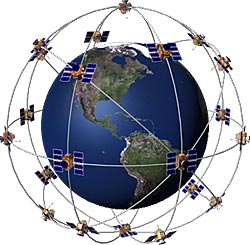
The GPS satellite system

The 24 satellites that make up the GPS space segment are orbiting the earth about 12,000 miles above us. They are constantly moving, making two complete orbits in less than 24 hours. These satellites are travelling at speeds of roughly 7,000 miles an hour.

GPS satellites are powered by solar energy. They have backup batteries onboard to keep them running in the event of a solar eclipse, when there's no solar power. Small rocket boosters on each satellite keep them flying in the correct path.

Here are some other interesting facts about the GPS satellites (also called NAVSTAR, the official U.S. Department of Defense name for GPS):

  • The first GPS satellite was launched in 1978.
  • A full constellation of 24 satellites was achieved in 1994.
  • Each satellite is built to last about 10 years. Replacements are constantly being built and launched into orbit.
  • A GPS satellite weighs approximately 2,000 pounds and is about 17 feet across with the solar panels extended.
  • Transmitter power is only 50 watts or less.

What's the signal?

GPS satellites transmit two low power radio signals, designated L1 and L2. Civilian GPS uses the L1 frequency of 1575.42 MHz in the UHF band. The signals travel by line of sight, meaning they will pass through clouds, glass and plastic but will not go through most solid objects such as buildings and mountains.

A GPS signal contains three different bits of information - a pseudorandom code, ephemeris data and almanac data. The pseudorandom code is simply an I.D. code that identifies which satellite is transmitting information. You can view this number on your Garmin GPS unit's satellite page, as it identifies which satellites it's receiving.

Ephemeris data, which is constantly transmitted by each satellite, contains important information about the status of the satellite (healthy or unhealthy), current date and time. This part of the signal is essential for determining a position.

The almanac data tells the GPS receiver where each GPS satellite should be at any time throughout the day. Each satellite transmits almanac data showing the orbital information for that satellite and for every other satellite in the system.

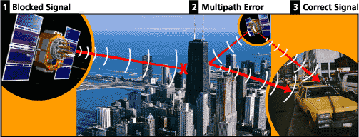
Blocked Signal Diagram

Sources of GPS signal errors

Factors that can degrade the GPS signal and thus affect accuracy include the following:

  • Ionosphere and troposphere delays - The satellite signal slows as it passes through the atmosphere. The GPS system uses a built-in model that calculates an average amount of delay to partially correct for this type of error.
  • Signal multipath - This occurs when the GPS signal is reflected off objects such as tall buildings or large rock surfaces before it reaches the receiver. This increases the travel time of the signal, thereby causing errors.
  • Receiver clock errors - A receiver's built-in clock is not as accurate as the atomic clocks onboard the GPS satellites. Therefore, it may have very slight timing errors.
  • Orbital errors - Also known as ephemeris errors, these are inaccuracies of the satellite's reported location.
  • Number of satellites visible - The more satellites a GPS receiver can "see," the better the accuracy. Buildings, terrain, electronic interference, or sometimes even dense foliage can block signal reception, causing position errors or possibly no position reading at all. GPS units typically will not work indoors, underwater or underground.
  • Satellite geometry/shading - This refers to the relative position of the satellites at any given time. Ideal satellite geometry exists when the satellites are located at wide angles relative to each other. Poor geometry results when the satellites are located in a line or in a tight grouping.
  • Intentional degradation of the satellite signal - Selective Availability (SA) is an intentional degradation of the signal once imposed by the U.S. Department of Defense. SA was intended to prevent military adversaries from using the highly accurate GPS signals. The government turned off SA in May 2000, which significantly improved the accuracy of civilian GPS receivers.

Motor On A Hall Effect Switch

Difficulty level: 2 (simple, but requires the use of a soldering iron)

Motor on a Hall effect switch

This is a simple and probably the most reliable motor. You may take a look at how easy it is to assemble this motor from the kit.

In 1879 Edward Hall placed a thin layer of gold in a strong magnetic field. He connected a battery to the opposite sides of this film and measured the current flowing through it. He discovered that a small voltage appeared across this film. This voltage was proportional to the strength of magnetic field multiplied by the current. This effect bears his name.

For many years the Hall effect was not used in practical applications because the generated voltage in the gold film was extremely low. However, in the second half of the 20th century the mass production of semiconductor chips started. Chips based on the Hall effect became inexpensive and widely available.

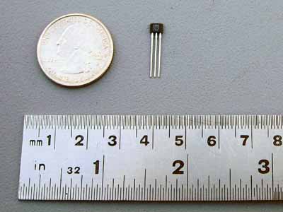
The Hall effect IC (integrated circuit) is a very small chip which includes many transistors. It consists of a thin layer of silicon as a Hall generator (which works better than gold) and several transistor circuits: to amplify the Hall voltage to a necessary level; to trigger output voltage with its growth; and to provide stable work regardless of the power supply voltage changes. The picture below demonstrates the Hall effect IC:

Hall effect IC

The Hall effect IC is a solid state electronic device with no mechanical parts and therefore it is more reliable than a reed switch. To no surprise it is now the most widely used sensor in industrial brushless motors. Normally, however, they include a lot of other components. Stan designed a motor on a Hall effect switch with minimum parts based on the same unified mechanical design and it worked very well.

The Hall effect IC used in Kits 6 and 8 (or available as a separate part) is a unipolar switch. It turns on and off when the South pole of the magnet passes by its branded side. The North pole has no effect on it, unless it approaches from the back side of the Hall IC. This Hall effect IC has a built in voltage regulator and may work in the range from 4.5 to 24V. The Hall effect IC's included in the kit, however, were tested extensively; and it was found that most of them start working at 3V. This is a typical Hall effect IC shown from the branded side:

Hall effect IC

The Hall effect switch output current is not sufficient to power this motor, therefore it also requires a power transistor. You may find information on this component at How It Works: Reed Switch Motor With A Transistor.

This is how this motor works:

  1. When magnet #1 gets close to the Hall IC, the sensor sends a signal to the base of the power transistor. The transistor opens, and allows a bigger collector current to flow through the electromagnet. The electromagnet pushes magnet #3 away.
  2. Diagram #1

  3. When the rotor spins away, magnet #1 stops affecting the Hall IC. Since the signal to the base of the power transistor has been removed, it is turned off. This disables the electromagnet.
  4. Diagram #2

  5. The rotor continues to spin due to inertia until magnet #2 moves into the working range of the Hall IC. The Hall IC sends a signal to the base of the transistor. The transistor opens, and allows a bigger collector current to flow through the electromagnet. The electromagnet pushes magnet #4 away. This process continues until the power is disconnected.
  6. Diagram #3

If you decide to design this motor yourself, you may order only the parts you need (Hall effect IC, PNP power transistor, magnet wire, magnets, heat sink).

Our experiments showed that the speed of this motor could be controlled by an extra magnet the same way the speed control unit works for the reed switch motors . The magnetic field of the additional magnet placed near the Hall effect IC interacts with the magnetic field of the magnets on the rotor. As you move this additional magnet the combined magnetic field becomes stronger or weaker depending on the orientation of the speed control magnet. It affects the time the Hall sensor sends the signal to the transistor and therefore changes the motor speed

Faraday's Law and Auto Ignition

Faraday's Law and Auto Ignition

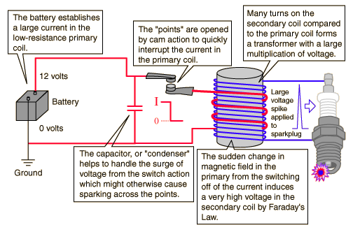
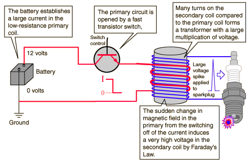
How do you obtain 40,000 volts across a sparkplug in an automobile when you have only 12 volts DC to start with? The essential task of firing the sparkplugs to ignite a gasolene-air mixture is carried out by a process which employs Faraday's law.

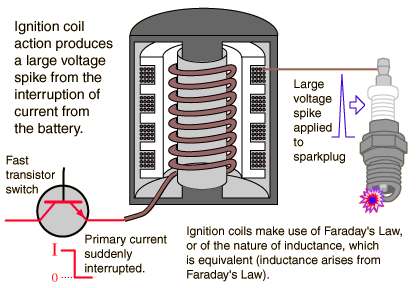
The primary winding of the ignition coil is wound with a small number of turns and has a small resistance. Applying the battery to this coil causes a sizable DC current to flow. The secondary coil has a much larger number of turns and therefore acts as a step-up transformer. But instead of operating on AC voltages, this coil is designed to produce a large voltage spike when the current in the primary coil is interrupted. Since the induced secondary voltage is proportional to the rate of change of the magnetic field through it, opening a switch quickly in the primary circuit to drop the current to zero will generate a large voltage in the secondary coil according to Faraday's Law. The large voltage causes a spark across the gap of the sparkplug to ignite the fuel mixture. For many years, this interruption of the primary current was accomplished by mechanically opening a contact called the "points" in a synchronized sequence to send high voltage pulses through a rotary switch called the "distributer" to the sparkplugs. One of the drawbacks of this process was that the interruption of current in the primary coil generated an inductive back-voltage in that coil which tended to cause sparking across the points. The system was improved by placing a sizable capacitor across the contacts so that the voltage surge tended to charge the capacitor rather than cause destructive sparking across the contacts. Using the old name for capacitors, this particular capacitor was called the "condenser".

More modern ignition systems use a transistor switch instead of the points to interrupt the primary current.

The transistor switches are contained in a solid-state Ignition Control Module. Modern coil designs produce voltage pulses up in the neighborhood of 40,000 volts from the interruption of the 12 volt power supplied by the battery.

Add more annotation to coil diagram

Some modern engines have multiple ignition coils mounted directly on the sparkplugs. Instead of single voltage pulses, they may under some engine conditions produce three voltage pulses. The coil arrangement shown is on a Dodge engine.

Faraday's Law

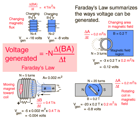
Any change in the magnetic environment of a coil of wire will cause a voltage (emf) to be "induced" in the coil. No matter how the change is produced, the voltage will be generated. The change could be produced by changing the magnetic field strength, moving a magnet toward or away from the coil, moving the coil into or out of the magnetic field, rotating the coil relative to the magnet, etc.

Further comments on these examples

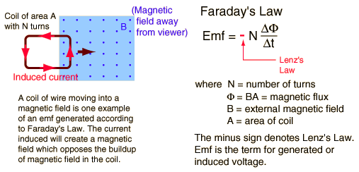
Faraday's law is a fundamental relationship which comes from Maxwell's equations. It serves as a succinct summary of the ways a voltage (or emf) may be generated by a changing magnetic environment. The induced emf in a coil is equal to the negative of the rate of change of magnetic flux times the number of turns in the coil. It involves the interaction of charge with magnetic field.

Lenz's Law

Lenz's Law

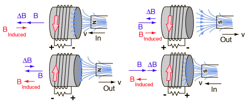
When an emf is generated by a change in magnetic flux according to Faraday's Law, the polarity of the induced emf is such that it produces a current whose magnetic field opposes the change which produces it. The induced magnetic field inside any loop of wire always acts to keep the magnetic flux in the loop constant. In the examples below, if the B field is increasing, the induced field acts in opposition to it. If it is decreasing, the induced field acts in the direction of the applied field to try to keep it constant.

UJT Relaxation oscilltor


Aim: -

To design and simulate UJT Relaxation Oscillator circuit.

Components: -

Name

EDWin Components Used

Description

Number of components required

UJT UJT Uni-Junction Transistor 1
RES RC05 Resistor 3
CAP CASE-A600 Capacitor 1
VDC VDC DC voltage source 1
GND SPL0 Ground 2

Theory: -

UJT is an uni-junction device. This single pn junction device consists of a lightly doped n-type silicon bar. The p- type impurity is diffused into the base producing the pn junction. The above figure shows the equivalent circuit of UJT. The resistance of the silicon bar is called inter base resistance RBB represented by the two resistors in series viz. Rb1 and Rb2. The pn junction is represented in the emitter by a diode D. The operation of UJT may be explained in three different modes.

  1. With no voltage applied to the UJT, the inter base resistance is given by
  2. Rbb=Rb1 + Rb2

  3. If a voltage Vbb is applied between the bases with emitter open, the voltage will divide up across Rb1 and Rb2.
  4. Voltage across Rb1,

    Or

    The ratio is called the intrinsic stand-off ratio represented by h . Thus . The value of h lies between 0.51 and 0.82. The voltage across Rb1 is which reverse biases the diode. Hence emitter current is zero.

  5. If a progressively rising positive voltage is applied to the emitter the diode will become forward biased when input voltage exceeds h Vbb by Vd, the forward voltage drop across the silicon diode. Now the emitter current increases regeneratively until it is limited by the emitter power supply. Here we can define the peak point voltage of the UJT,

.

Thus when input positive voltage to the emitter is less then Vp, the pn-junction remains reverse biased and the emitter current is practically zero. When the input voltage exceeds Vp, the diode is forward biased and the emitter current reaches a saturation value limited by Rb1and the forward resistance of pn-junction.

UJT Relaxation Oscillator circuit, mainly used for triggering purposes is shown above. This circuit is ideally suited for triggering an SCR – since UJT is capable of generating sharp, high powered pulses of short duration whose peak and average power don’t exceed the power capabilities of the SCR gate for which they are intended. When power is applied to the given circuit, capacitor C starts charging exponentially through R to the applied voltage VCC. The voltage across C is the voltage-Ve applied to the emitter of UJT. When C is charged to Vp, then UJT turns ON. This greatly reduces the effective resistance between emitter and base1 of UJT. A sharp pulse of current flows from base1 to emitter, discharging C through Rb1. When the capacitor voltage drops below Vp, UJT is brought back to the previous state and the capacitor again begins to charge towards Vbb. This produces a sawtooth wave.

In the circuit diagram shown above Rb1 and Rb2 are used to protect UJT from overheating. This inturn provides sharp pulses across them: Rb1 produces a positive spike and Rb2 produces a negative spike.

Design: -

Oscillator frequency

Intrinsic stand-off ratio h =0.4 to 0.6

h =0.5 (we take)

substituting the value of h in (1)

Capacitor C is charged through R towards supply voltage VBB. As long as capacitor voltage VE is below a stand-off voltage VP set by the voltage across B1-B2 and the transistor stand-off ratio h .

Sweep Amplitude = VP-VV

from design specification

Design of R

At peak point emitter voltage VE=VP and current through R is given by

At valley point

Design of Capacitor

Design of RB1 and RB2

At the point where the capacitor voltage is equal to VP assuming IE=0A, the network of fig 4 results. VP is the voltage required to turn on the UJT.

But the intrinsic stand-off ratio h is given by the equation

Also

Substituting (a) and (b) in equation (10) we get

RB2 is chosen as a low value resistor. Let it be 100W .

Hence the above equation becomes

Procedure: -

EDWinXP -> Schematic Editor: The circuit diagram is drawn by loading components from the library.Wiring and proper net assignment has been made. The values are assigned for relevant components.

EDWinXP -> Mixed Mode Simulator: The circuit is preprocessed. The test points and waveform markers are placed at C, Rb1 and Rb2. The Transient Analysis parameters have been set. The Transient Analysis is executed and output observed in the Waveform Viewer.

Result:

The output waveform may be observed in the waveform viewer.